This step is totally optional but I typically sand, seal, sand, and polish all of my carbon fiber pieces. The results are mirror finish edges and a smooth tactile feel when you handle the car.
The F104 X1 comes with an FRP lower and upper deck as well as a carbon fiber battery hold down plate. This is my first experience with the latest FRP material that Tamiya utilizes and the quality of the cuts were a pleasant surprise. For the FRP parts, I skipped the CA sealing and went straight to wet sanding starting at a 180 grit and finishing with a 1500 grit. Afterwards, I polished the edges with Mother’s Polish. The finish isn’t as mirror smooth as it would be if it was carbon fiber, but for my first FRP chassis, it’s good enough.
Setting up for chassis prep:
Step 0 – Chassis Prep

Close up of raw carbon fiber edge:

On the carbon fiber piece, I wet sanded with 180 grit to knock off the sharp edge and then applied two coats of CA with a cotton swab.
A couple of tips on sealing with CA:
• Avoid using glue under fluorescent light. The UV rays accelerate the cure time and yields a rough, crinkly surface.
• Try to seal with a warm ambient temperature, somewhere between 75-90 degrees F. If it’s too cold, a white residue will form.
• Be patient and apply thin layers allowing proper drying time between coats.
After applying the CA I set the carbon fiber piece aside to completely dry. The area I’m taking photos in is full of fluorescent lighting and would really mess it up. I’ll post pictures later
Bearing Prep:
I took all of the axle bearings and did an initial blow out of grease with a quick hit of motor spray. I then placed them in a jar of motor-spray and set them aside to marinate until needed. Again, this is only for the axle bearings…I did not do this for differential bearings. Also, keep in mind this trick is intended for spec, silver-can, or slow motor racing and bearing life will be shortene

That’s it before starting on step 1.
The first step is rather straight forward. It involves attaching the rc tray posts, the hi-traction T-bar and the bottom of the motor pod to the lower deck.
Step 1
Here are all the parts for Step 1:

Weight of kit supplied hardware instructed for use in step 1:

Weight of titanium and aluminum hardware I will be using in step 1:

Low profile nut:

I used a low profile 3 mm aluminum nut and a 3x6mm countersunk screw instead of the kit setup to free up additional wiggle room when you slide batteries in an out of the chassis. This yields at least an additional 1 mm of clearance so you don’t scratch your batteries up when you slide them into the chassis at an angle. Please note the liberal use of blue locktight to keep the nut in place.
Step 1 completed:

Step 2
Step 2 involves assembly of the motor mount. It is very important to assemble the pod on a flat surface to prevent any tweaking which could potentially lead to an ill handling car.
Parts and an aluminum motor mount for step 2:

Weight of kit hardware:

Weight of titanium hardware:

Loosely assemble the motor mount:

I assembled the motor mount on my setup board and did not fully tighten any of the screws.
While holding the motor mount flat, tighten each screw a little bit at a time, alternating between different screws until all of them are snug:

Now you can apply Kong-like strength and tighten the screws completely
This concludes step 2.
Step 3
Step 3 is a no brainer and I am contemplating if I should even post it. I’ll post some more after a little break.
Okay, I’ll post this step before taking a break… Attaching the motor mount to the chassis. Four 3x8mm countersunk screws…that’s it.
Parts for step 3:

Weight of kit hardware:

Weight of titanium hardware:

Step 3 completed:

Step 4
Hardware weight savings so far: a whopping 4.9 grams hehe
Step 4 involves attaching the rear drive shaft as well as ball studs for the shock and side damper.
Here are the parts used for step 4:

Acer synthetic is the only oil I ever use. It’s a light oil and works very well for just about anything. Although the bottle has great eye candy, it doesn’t have a needle tip, so I have a spare bottle with that.
Also pictured is carbon fiber rear shaft. I’m all for low rotational mass and if you can put the power down, it’s a significant advantage.
Steel shaft:

Carbon fiber shaft (that’s what I’m talking about):

A little glue goes a long way:

To prevent cracking or premature wear from constant screwing (hehe), a drop of CA was carefully spread across the flat spots on the CF shaft. If the CA goes anywhere except for the flat spot, the bearings supporting the shaft will be difficult to install. If that’s the case, and you can see I had a little oopsie, spinning the shaft in some 400-600 grit sandpaper should remove the excess CA.
When I first saw these ball studs, I thought “Sweet, black anodized aluminum good stuff!” Then when I held them in my fingers, they felt a little bit too heavy to be aluminum…
Kit ball studs:

Aluminum hop ups:

Free speed:

Remember those bearings in the jar? I removed them and gave them another blast of motor-spray to get rid of any residual grease. Once dry, I applied the synthetic oil:
Now that the CF shaft and bearings are ready, it’s time to prep the parts that hold everything together.
Locktight set screws:

I used blue locktight on the set screws for the diff joint and wheel axle. With locktight, I do not have to over tighten the set screws and risk cracking the CF shaft. It should be tight but not carbon fiber-cracking tight.
Step 4 completed:

Step 5
The counter weight is a neat idea, it doesn’t effect rotating mass and acts like a spinner
Using the number 2 ride height adjuster to keep rear ground clearance to a minimum.
Important tip, when stacking all the pieces onto the rear motor pod, you want the shaft to have a microscopic amount of side to side play. Maybe 0.05mm, just enough to ensure that the shaft assembly floats freely and none of the bearings will bind. It took several attempts, but with enough patience and adjusting, I was satisfied with the result. Again, this is a free speed tip . Rear wheels will spin forever.
The ball differential is a vital component that affects the way the car handles. During assembly, I made sure that I kept all parts clean and free of contaminants.
You can use your grease of choice based on what’s popular at your track. For the Tamiya track, there’s a mix of those who run normal greases and those who run Mobile 1 red synthetic grease. Back when we used to run rubber tires on the F103, all of the really fast guys ran Mobile 1 grease religiously. We set the differential to slip between 6 inches to 1 foot under full acceleration from a dead stop. Keep in mind, there is a fine balance and requires a bit of time and effort finding the sweet spot, but once you nail it, you can hammer the throttle on corner exit without any surprises…and that is a good feeling.
That being said, I deviated on this build by building the differential similar to my touring cars. Associated red label silicon grease on the plate and balls, and Mobil 1 or Tamiya’s VG thrust bearing grease on the thrust bearing.
Important tip: When assembling the differential, do not fully tighten the lock nut. You want to snug it up until the differential action starts working. Fully tightening and loosening a quarter turn as instructed by the instructions may crush or deform the diff plates, diff balls, or thrust bearing. Final adjustments should be done at the track after break-in of the diff.
Parts and a few hop-ups for step 5:

Building the diff with AE red label silicon grease:

After assembly, the differential action felt somewhat dry and gritty. I wasn’t satisfied with this and took it apart and degreased everything.
If you noticed in the previous pictures, I was using the hop up thrust bearing. There’s a reason why we never used it when we ran F103 rubber cars. The were inconsistent as some would be great out of the pack while others were junk. They didn’t last long either with the way we set our cars up to slip. Lastly, there was a time when we had a huge supply of stock thrust bearings; we wouldn’t think twice tossing out a semi-worn one and replace it with a new one…just because we had so many .
Okay, so now that everything was taken apart and degreased. I rebuilt the diff with Mobil 1 and used the stock 1150 bearing with cone washers as the thrust bearing.
Rebuilding the diff with Mobil 1 synthetic grease:

Step 5 completed:

Ah…smooth like butter.
Step 6
Step 6 is devoted to differential gear adjustment. Since, this is something I do at the track after breaking in the diff, I’ll skip this step.
Step 7
Step 7 involves attaching the diff cap onto the diff hub and installing the motor. I typically install electronics last and will post info when I get to that step.
Parts for step 7:

Not much to it, step 7 completed:

Step 8
Moving to the front end, step 8 involves attaching the front lower arm and camber plate.
Parts for step 8:

Weight of stock hardware:

Weight of hop up hardware:

What happened here?!?
The two stock 4x30mm screws are actually aluminum and weigh much less than their titanium counterparts. I like the weight of aluminum but want the strength of titanium. That being said, I split the difference and used an aluminum screw for the front and a titanium screw in the rear.
Step 8 completed:

Step 9
I initially set camber to 1.5 degrees since it seems to be a moderately safe amount of camber. I will add or remove camber while testing setups. For reference, my F104 Pro is currently set to 2.0 degrees. Oddly enough, at least at the Tamiya track and on MY F104 Pro, adding front camber seems to effect only entry and mid corner steering…it has no effect on corner exit. Please let me know if you’ve experienced something similar. Or you can tell me to put the crack pipe down .
Note, I used a tiny dab of blue locktight on the camber ball studs to keep them in place. The use of locktight here is totally optional but I used it for a sense of security. Again, I used a very small amount.
And that completes step 8. The next steps contain a mix of chassis assembly and electronics installation. As I said earlier, I tend to install electronics last, so I may be skipping or jumping steps in my subsequent posts.
I’ve got a Saturday to get out and enjoy so I won’t be working on the car until this evening. Tomorrow is a practice day so time to work on the car and post info will be limited.
Tie-rod assembly is a breeze if you have the right tools.
Parts for step 9:

Adjuster tool and turnbuckle wrench doing work:

To ensure straight tie-rods, I typically start threading an adjuster onto a turn buckle and try to get it as straight as possible during the first few threads. If it isn’t straight, back off and try repositioning. From there, you can go to town with the tools.
Trimming adjusters with a sharp exacto blade:

Step 9 continued…
Weight of stock hardware:

Weight of aluminum hardware:

Continuing with step 9, I used a dab of blue locktight on the steering horn assembly:

Step 9 completed:

Step 10
I didn’t get much accomplished with actually building the car today. However, I did work on the electronics.
Heat-shrink and shoe goo hides most of the wiring mess:


To continue with carbon fiber prep from one of my earlier posts, this is how the carbon fiber edges looked raw:

After wet sanding with 240 grit to remove sharp edges and application of two CA coats.

Not bad, but it can get way better.
Once the glue dried, I wet sanded the glued edges to smooth them out. I started with 400 and used finer grits until I got to 2000.

Pretty smooth…
Now it’s time for the fun stuff.

Close up of the finished carbon fiber edge:

Steps 11-13
Apologies for the craptacular picture. It was impossibly hard to get the camera to focus because of reflections and highlights on the shiny edges.
Hopefully this gives you some into the process I use for prepping carbon fiber parts. It’s time consuming but the results are awesome.
Steps 10 through 13 involve assembly of the servo saver and installation of the servo and electronics trays.
Parts for the famous or infamous Tamiya heavy duty servo saver .

If you look carefully, I went back to step 9 and flipped the ball connectors on the aluminum servo horn. From my experience with the F04, I liked the way this setup felt on track. Additionally, this may help offset any ackerman effects that occur due to extreme tie rod angles. This is something that you should test on your own and decide which way feels better because of different driving styles and individual preferences on how the car should feel.
Servo installed

I trimmed off some plastic near the front front of the servo holders in case I want to play with additional steering geometry in the future . I have in the past, but I actually prefer the stock servo position. This is one of those “just in case” moments.
Adjuster clearance

Step 14
There’s not much room, but the adjusters clear the servo and mounts with no binding or rubbing.
Also, I’ve given up on providing weight comparisons between stock and hop up hardware for individual steps. It’s a work multiplier and slows down the build tremendously. Besides, I think we should get the idea by now; the car will be lighter than stock.
I added a bunch of hop-up goodies during the assembly of the upper deck.
Parts for step 14

Step 14 completed:

Step 15-16
The aluminum body posts weigh a little more than the plastic ones, but these are pimp and are faster than the stock . I swapped the titanium screw that holds the TRF415-7 antenna holder to an aluminum one…less weight and no stress on an antenna.
Parts for step 15

Not much to this step with four screws and two o-rings.
When attaching the upper deck to the chassis, make sure you use a flat surface to keep the chassis as flat and straight as possible while you tighten the screws.
Step 16 shows instructions on attaching the R/C units to the chassis. Since I’ve already completed that step, this step no longer applies.
Steps 15-16 completed

Step 17
It’s starting to look like a car .
Attaching the front upper arm is straight forward with no drama.
Parts for step 17

During initial assembly, it will be easier to screw the ball connector nut to the chassis before you attach the front upper arms.
Step 17 completed

Step 18
Step 18 calls for assembly and attachment of the front uprights.
Parts for step 18

Please note the following:
• The kit provides all three different springs. Nice!
• I replaced the plastic spacers with aluminum spacers. Precision!
• I used black springs with Tamiya soft damper grease to provide some form of damping
To help keep everything in place, use blue locktight on the 2mm nuts and 3mm grub screws

Before I tighten the grub screw completely, I pinch the steering upright up against the upper arm. I’m not certain if doing this affects anything, but it can’t hurt.
Step 18 completed

Steps 19-22
These steps involve the assembly of shock and roll damper. Not much more can be said about the TRF damper that hasn’t already been said before. It’s simply the best out there.
Parts for steps 19-22

Note the following:
• I added a 0.1mm spacer between the bottom c-clip and shock piston. This reduces any slop that the piston may have.
• The instructions call for Tamiya ball diff lube for the roll damper. Since this is the first X1 I’ve built, I will go with that. After putting the roll damper on the car, it does feel a little light but very smooth and may just work for the Tamiya track.
• I was pleasantly surprised when I opened the parts bag to found out that the kit comes with 3 springs for the rear shock. The red spring feels almost like the old gold miata spring and that’s what I used.
• Assembly of the TRF damper is pretty much a no-brainer. While putting the shock together, I used a drop of shock oil on the orings, rod guides, and shock shaft,
0.1mm spacer on top of the shock shaft’s c-clip

Steps 19-21 completed

Dampers attached, step 22 completed

From another angle

Once everything was together, the damper feel seems to be very promising. It’s got that floppy loose feel, but is smooth at the same time.
That pretty much covers the assembly of the chassis. With the exception of a few minor pieces, the car is very close to being finished.


Things to do before the car is ready to run include initial setup, setting steering toe angles, adjust steering end points on the radio, glue tires, mount body, break in of the diff, etc…If you want, I’ll post more information about that when I finish prepping the car for it’s maiden run.
I hope this build has been informative and I thank you for taking the time to view it.
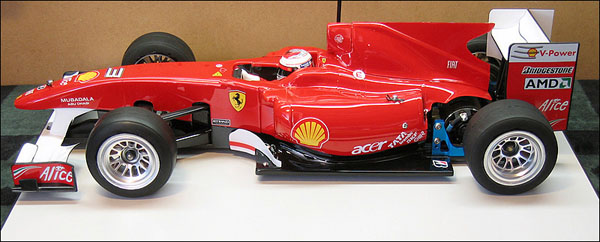
I took some time today to finish the car and get it ready to run.
Left side of the F104 X1 with an F60 body set

The right side shot

Please note the following details:
• As instructed, don’t forget a dab of grease on the lock nuts to prevent the locking rubbery bit doesn’t rip or pop off when you initially tighten it.
• When attaching the front wheels, tightening the lock nut fully and then back off an 1/8th of a turn to prevent the bearings from binding.
• I had to adjust the rear body mounts by adding/removing spacers until I was satisfied with the body’s stance.
• The body MUST be trimmed to clear the roll damper.
• Trim ANY part of the body that may rub ANY part of the chassis when it’s flexed in ANY direction. This will prevent any weird on track behavior due to a body rub.
Close up of left side body trimming

Close up of right side body trimming

And with these minor odds and ends wrapped up…the F104 X1 is DONE
One comment
Pingback: Topeka Onroad Racing - Page 593 - R/C Tech Forums